Playing toys means a whole lot of beneficial explanations for children's improvement and these aren't just meant to keep them busy. Kids know the way to socialize with other people by means of playing. Associative plays allow a kid to get along with other people. Moreover, children will also develop and master their intellectual and also motor abilities through playing toys. Because of this, kids always find and request for toys.
Yet, there's a wide array of toys available in the market; thus, people have to be meticulous with their pick. There are those that will help in the child's improvement while there's also those that could be dangerous. Small children are extremely curious and love to explore a lot, so parents must be extra careful in selecting toys for them.
It must not have minute parts that may result in choking. Furthermore, you have to go for toys making use of non-toxic and BPA free materials. With a whole lot of toy companies, picking which to rely on could be an issue. Yet, the top name for toys is none other than John Deere Toys.
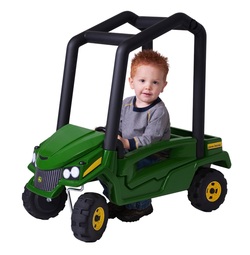
The pioneer John Deere toys for toddlers are simple pedal tractors. In addition, a trademark was made by the company making their ride on tractors having green and yellow tints. Lately, they have produced toys with different colors. The company produced brand new ride on toys for girls and some of these include pink bikes. better resources at bestcheapbabystuff.com/ride-on-toys/john-deere-toys/
Wheel burrows, barn play sets and ride on tractors are the common toy collection of the company. Toys for older kids are also offered; these incorporate motorized pedal tractors that they'll definitely enjoy. With regards to trustworthiness, each of their toys is made out of die cast steel.
Kids deal with their toys very roughly, so the toys are particularly made to be long lasting and high in quality to make them last for years. John Deere Toys also created other toys just like big-tire three wheeled bikes, puzzles, two wheeled bikes, games and tool boxes, tricycles and also wooden model paint kits apart from their famous tractor collection.
With superior quality and affordable price, these toys are the finest for your children. The best toys for your cute children are no other than John Deere toys for toddlers.
Yet, there's a wide array of toys available in the market; thus, people have to be meticulous with their pick. There are those that will help in the child's improvement while there's also those that could be dangerous. Small children are extremely curious and love to explore a lot, so parents must be extra careful in selecting toys for them.
It must not have minute parts that may result in choking. Furthermore, you have to go for toys making use of non-toxic and BPA free materials. With a whole lot of toy companies, picking which to rely on could be an issue. Yet, the top name for toys is none other than John Deere Toys.
The pioneer John Deere toys for toddlers are simple pedal tractors. In addition, a trademark was made by the company making their ride on tractors having green and yellow tints. Lately, they have produced toys with different colors. The company produced brand new ride on toys for girls and some of these include pink bikes. better resources at bestcheapbabystuff.com/ride-on-toys/john-deere-toys/
Wheel burrows, barn play sets and ride on tractors are the common toy collection of the company. Toys for older kids are also offered; these incorporate motorized pedal tractors that they'll definitely enjoy. With regards to trustworthiness, each of their toys is made out of die cast steel.
Kids deal with their toys very roughly, so the toys are particularly made to be long lasting and high in quality to make them last for years. John Deere Toys also created other toys just like big-tire three wheeled bikes, puzzles, two wheeled bikes, games and tool boxes, tricycles and also wooden model paint kits apart from their famous tractor collection.
With superior quality and affordable price, these toys are the finest for your children. The best toys for your cute children are no other than John Deere toys for toddlers.
 RSS Feed